The present article is a brief review of electric power transmission systems, with special attention to overhead power transmission lines, their aspects and costs.
Introduction
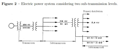
An electrical energy system formed by generators, transformers, transmission lines and distribution feeders can be seen as shown in the diagram in the next figure. Note that the operating function of generators is to transform mechanical energy into electrical energy, in order to inject electrical power into the transmission network, which, for economic reasons (loss reduction), commonly transmits electrical energy under high voltages (eg 345 kV, 500 kV or 700 kV). Note that generators are usually present in locations far from the load centers and, therefore, they inject the power generated into the grid through transformers, which are intended to transform the power generated from the voltage levels of the generators to the levels of voltage of the transmission lines. Then step-down transformers reduce the transmission voltage levels to voltage at the distribution level to make the generated and transmitted power available to final consumers.
Note also that, according to Camargo (2006), an electrical power system is defined as
being of good quality, or better, as being of reliability, when it has continuity, compliance, flexibility and maintainability. Therefore, large financial investments and a complex development of equipment and construction of structures are necessary to meet the aforementioned requirements, considering that, in particular, the transmission network covers large territorial extensions and is integrated with the distribution systems and, it also enables the interconnection between neighboring systems in order to obtain technical and economic benefits.

Therefore, based on the need to transport electricity from generation to consumers with good quality and in an economically accessible way, the option arises between transporting the primary energy used in generation (for example, thermal based power plants) or by transporting electricity (eg hydroelectric plants). In addition, in general, the cost of transporting electricity increases as the distance between generation and the final consumer increases, as well as this cost is reduced with the increase in the amount of energy to be transported. Therefore, the constant verification of the evolution of the electric energy market accompanied by network expansion studies are essential to determine where to apply the financial resources related to the development of transmission lines and their protection systems, acquisition of equipment and modernization, re-powering, construction of a system and commissioning, operation and maintenance of the transmission network, in a market where all these variables closely accompany the growth and development of countries.
Transmission Lines
In order to perform the transport of electrical energy it’s used conduits in the form of overhead lines or cables, underground or underwater. And they have the following distinctions in general (see Figure 2), according to the voltages and the amount of energy they carry.

- Transmission lines – In general composing the lines that operate at the highest voltages in the system and are responsible for transporting energy from generation centers and consumption centers, as well as for the interconnection between independent systems.
- Sub-transmission lines – These are lines that operate at voltages commonly lower than those of transmission lines (not being a rule), and their function is to distribute the energy transported by the transmission lines in bulk.
- Primary distribution lines – They make up the lines with lower voltages and occupy public roads in a safe location, thus allowing for good regulation and service for reasonable powers.
- Secondary distribution lines – These are the lines that operate at the lowest voltages in the system and commonly do not have a length exceeding 200 to 300 m. In such a way that its tension allows direct use in electrical machines, lighting and household appliances. In Brazil at particular, systems are used in 220/127 V (between phase and neutral and between phases) and the 380/220 V system, derivable from single-phase systems.
Finally, based on the definitions above, it can be seen that the good performance of a transmission line is part of an adequate characterization of its purpose, as well as an adequate choice of its constituent elements. And, as can be seen below, some components commonly used in overhead power transmission lines are described.
Transmission Towers
In general, transmission towers are part of the transmission structures and their main objective is to support the conductor cables and their associated elements, such as insulators, hardware and lightning conductor cables. The conductor cables can be arranged in the structures according to a triangular, horizontal or vertical position.
Insulators
Insulators are used to connect the conductor cables to the transmission towers, whose function is to electrically insulate the energized conductors of the transmission structures, as well as resist the mechanical and electrical stresses arising from the conductor cables. Furthermore, they can be manufactured in porcelain, glass or synthetic technology. Note that in transmission lines two types of insulators are usually used.

- Pin-type insulators - they are attached to the frame using a steel pin. Up to 69 kV voltages are normally used.
- Suspension-type insulators – typically used for voltages above 69 kV. In addition to having advantages over pin insulators in high-voltage and extra-high-voltage lines, such as replacement costs in case of replacement and flexibility of suspension chains.
By the other hand, the hardware of the transmission lines correspond to metallic elements, manufactured, for example, in steel or aluminum and are designed to resist electromechanical efforts and even reduce electrical effects, such as radio interference and corona. There are, therefore, several types of hardware, each with a specific function in transmission lines, and their specifications and designs depend on the manufacturer and meet regulatory requirements. For example, there are the clamps responsible for the mechanical interconnection between the chain of insulators and the structure, in addition to transmitting different efforts to the tower.
Cables
Through conductor cables, there is the process of transmission of electrical energy in a transmission line. In theory, an ideal conductor has high electrical conductivity, good mechanical and weather resistance, low weight and low manufacturing costs. Thus, aluminum is the material most used in the manufacture of electrical conductors, given its low market cost, compared to copper, for example, which is most used in installations buildings, commercial and industrial. For practical purposes, comparing both materials, the investment with aluminum conductors is approximately equal to 25% of the investment required with equivalent copper conductors, for similar performance. Despite the lower mechanical strength of aluminum compared to copper, which can be compensated for with aluminium-steel cables.

Lightning Rods
On the top of the tower structures, lightning conductor cables located just above the phase conductors are intended to protect the phase conductors against lightning strike and consequent damage or interruption of the system. These cables are generally manufactured with a smaller cross section than phase conductors. In addition, the cables are grounded in the tower. In this way, when lightning strikes a shielded wire, it flows without causing damage to the system, as long as the impedance and resistance of the tower legs are small.
Cables Installation
Once the cable support structures have been assembled, the installation step of the lightning rod cables begins, which includes the activities of launching, splicing, arrowing and clamping, in accordance with the technical specifications and safety standards. Note that the laying of
cables is carried out based on the Launch Plan, where the conditions and obstacles of the tracing of the transmission line are evaluated, so that the distribution of the coils in the field can be
improved so that the installation of the cables is carried out with less material waste and greater optimization. Then, after starting the launching start and end locations in each stretch, the order of positioning the coils, splice locations, arrow control spans and the locations of protections actuators, if applicable, on highways, railways or other transmission or distribution lines, therefore, the laying of the lightning rod cables at the top of the tower is started, followed by the laying of the conductors. Also note that, in extra high voltage transmission lines, the cables are laid under controlled tension, that is, a steel cable, called pilot cable, is launched first, for later connection of the cables stipulated in the project in the pilot through a rocker arm. The cables are, therefore, pulled by a winch located in the winch square, while at the other end, called the brake square, the cables exit the reels and pass through the brake, where the release voltage is controlled (see the Figure 6). In addition, the number of spools to be used depends on the length of the transmission line and, in general, such spools are wound on wooden supports with the capacity to transport about 2 km of cable.

Signalization
In Brazil, the installation of signaling items along the transmission lines is the responsibility of the contractor and has the objective of ensuring safety, identifying and alerting to the particularities of the project. In general, they are usually installed after the end of the cable installation and must follow the criteria established by NBR6535/2005.
Note that usually uses spheres that have a diameter of 60 centimetres and a spacing of
30 m between them (next figure). In addition, they are painted in orange or red, in order to assist
aircraft pilots and other air activities under the presence of transmission lines.
Planning a Transmission System
According to Fuchs (1977), 80% of accidental interruptions in power supply originate in or are caused by transmission lines. Therefore, transmission systems and their reliability are of fundamental importance for the development of a country, and are also the object of planning studies of different natures. However, in general, starting from a systematic analysis of the evolution of the electric energy market, there is, therefore, the first stage of the electric energy transmission planning process. Thus, through economic reports of energy growth and knowing the peak load values along the system’s buses and within a given analysis range, studies can be carried out in order to design a basic system of transmission. In this phase are models and hypotheses of the planning of transmission lines and also the basic topology of the transmission network. Then, through simulations, several hypotheses related to possible disturbances in the network are tested and verified. And then compensatory studies are carried out in order to mitigate the possible disturbances found and that will be necessary for the network. Furthermore, the economic analysis is carried out considering transmission losses and the most feasible technical aspects applied to the project, so that the sum resulting from the investment cost, the cost of losses and the cost of system reliability is viable. Still in the planning phase, the conception or basic guidelines of the protection system are also considered. Thus, after the design phase, the stages of civil construction, hiring of labor and services are carried out, as well as the acquisition of equipment, commissioning, operation and maintenance of the transmission system.
Costs Analysis
In general, the calculation involving costs and budget is directly related to the quantities and unit costs of specified materials and services. Therefore, all the elements that influence the final value are included and organized according to the activity to be achieved and its partial costs, so that, in the end, it is possible to calculate the total cost of the project. Note that the final costs of installing a transmission line are linked to the cost of civil construction materials, which vary in price depending on the location of the work and distance from major centers. Another important factor in the final cost concerns the power to be transmitted, which will directly influence the gauge of the cables, the weight of the structures and, therefore, the making of the foundations. However, labor costs are also mentioned, which are calculated by the concessionaires through the Collective Labor Conventions and Agreements, so that the base salary values are defined according to the minimum required work conditions and depending on the region. Finally, the taxes levied on materials, services and social charges accounted for are also considered. Thus, once all costs are added, they are divided into direct, indirect and eventual costs, so that together they provide the final cost of the project. For example, in Table 1, the costs of individual components are shown as percentages of the total cost involved in works on electric power transmission lines.

Therefore, note that, among the various electric energy transmission systems, the final cost is of fundamental importance as a determining factor in making the choice of installation or expansion of a system. Figure 8 shows a brief comparison between the installation cost as a function of the transmission line length.
Load Curve (Demand)
In modern transmission systems, checks are carried out on the consumption characteristics for a given load center served, so that through a load curve relating the measured consumption and a given period of time (see Figure 9) it is possible, then, to determine parameters that help in guaranteeing the supply of reliable and economical electric energy adequate to the consumer. Note that, in Brazil, according to Normative Resolution No. 414/2010 of the National Electric Energy Agency (ANEEL), the ratio between active energy consumed and the maximum energy that could be used in a given time interval. And, in turn, still defined by the same resolution, there is the demand factor as the ratio between the maximum power demand registered in a specified time interval, or supply power, and the installed power in the consumer unit.

Therefore, from the analysis of the load curve, it is possible to carry out the verification of the load factor and, thus, identify the peak demand points and evaluate the uniformity of electric energy use, with a view to better utilization of the electrical system.
Planning the Expansion of Power Transmission Systems
Considering that, for the most part, electricity transmission consists of the transport of electricity between generation and consumer centers, therefore, the transmission network comprises the basic infrastructure which allows the flow of electricity in power systems. Therefore, transmission networks have physical restrictions to this energy transport, thus, not all energy dispatch solutions are viable. Therefore, it is necessary to plan the expansion of electricity transmission systems, that is, planning that can make it possible to decide which interventions on the lines will allow the system to meet future loads of greater demand with safety and reliability. In addition, the expansion plan may require the introduction of higher voltage levels, as well as the installation of new transmission elements and new substations. Therefore, transmission expansion planning is a non-linear optimization problem that varies with complexity and computationally in relation to demand.
Therefore, according to Verly e Oliveira (2017), the planning for the expansion of transmission systems aims to determine a set of circuits, so that the system will operate properly within a previously known planning horizon, and with the least investment possible. Thus, it is a difficult problem to solve, given that
- It has multiple points of minimum local, which leads most algorithms to premature convergence to a point of optimal local;
- It has a combinatorial nature of the decision process, which can lead to high processing time;
- There is the possibility of existence of unconnected electrical systems, that is, that require special treatment to avoid singularity problems during the optimization process.
Planning Horizon
In the literature, the planning of transmission systems expansion in relation to a planning horizon is approached through static or dynamic views, that is, the static approach considers a single stage where there is only the present and the future. On the other hand, dynamic approaches enable a holistic view of the problem, resulting in more robust and efficient planning over time.

Therefore, in static planning, the planner seeks an appropriate number of new circuits that must be incremented on each branch of the transmission system and, in this case, the planner is not necessarily concerned with defining when the new lines must be built and the total cost expansion is carried out early in the planning horizon. On the other hand, the dynamic approach considers multiple stages, while an ideal expansion strategy timetable is considered for the total planning period. This type of approach in general constitutes a problem of greater scale and greater complexity, as the appropriate moments to carry out such investments are considered in addition to investments.
Solution Methods
Basically, in the literature, three big groups of algorithms are used to solve the transmission system expansion problem can be evidenced:
- Constructive Heuristic Algorithms – these algorithms use continuous optimization techniques, are robust and commonly find a good quality solution with little computational effort, however, it is not common to find global optimal solutions, especially when dealing with real and/or large systems.
- Classical Optimization Algorithms – they make use of mathematical decomposition techniques and generally find global optimal solutions for small and medium-sized systems, however, for large systems, such algorithms can present problems of convergence and of great computational effort.
- Combinatorial Algorithms – they find optimal or sub-optimal solutions, including for large systems, but with high computational efforts.
Therefore, given the above characteristics, it is important to understand the decision maker’s needs. Since simple modeling provides fast mathematical solutions with acceptable cost estimates of the real behavior of the power system. On the other hand, the more robust and realistic the model, the greater the computational effort needed to obtain a relevant solution, showing that there is a direct relationship between the complexity of the adopted approach and a possible convergence to minimum local . Table 2 summarizes the advantages and disadvantages of the solution methods mentioned above.

Considering that the problem of planning the expansion of transmission systems involves different natures and behaviors, as Gomes and Saraiva (2019), this problem can be categorized into six groups of elements which are associated with different models, as it can be seen in Figure 11.

Note that there are several optimization techniques proposed to solve the transmission system planning problem. Such techniques are generally classified into mathematical, heuristic or meta-heuristic models and below, there is a summary of the main techniques. Furthermore, from the point of view of modeling the problem, there are basically two solution models, that is, an AC model and a DC model, where the latter has as disadvantages the fact that the reactive power is not considered, the plan The resulting solution must be reconsidered when AC operation in the system is considered and also given the difficulty of considering losses in the DC model. On the other hand, the AC model presents as main advantages,
- Consideration of reactive power in planning;
- Reactive reactive power can be reviewed when planning to reduce lines;
- Transmission losses are fully considered;
- Other studies such as voltage stability can be considered.
And it has as disadvantages
- The AC model leads to a complex and non-linear programming problem;
- Efficiency optimization techniques are needed to solve the AC model;
- Managing disconnected systems, a common situation at the beginning of transmission planning, where generators and loads have not yet been electrically connected to the grid.
Expansion Planning From the Modeling Point of View
During the initial considerations of the planning problem, several variables and objectives come into conflict with each other, so that in traditional planning, the objective is basically to reduce costs. On the other hand, in advanced planning, other goals are considered, such as
- Optimize competitiveness among market shareholders;
- Mitigate transmission congestion;
- Minimize risks;
- Improved reliability and security;
- Considerations in distributed generation;
- Minimization of environmental impacts.
Below are some models of proposed solution based on the problem of expansion of the electric power transmission system.
Mathematical Optimization Methods
- Dynamic programming – Also called discrete dynamic optimization (DDO), it was proposed by Dusonchet e El-Abia (1973) to solve the transmission planning problem. And basically, this method combines the deterministic search procedure of dynamic programming with the discrete optimization of a probabilistic search together with a heuristic stopping criterion;
- Linear programming, non-linear programming – This method was proposed by Garver in 1970 and was originally applied to the long-term planning of electric power systems, in order to produce a viable transmission network containing minimal amounts of circuits using any existing network as input, in addition to considering a given load forecasting and generation schedule;
- Hierarchical decomposition – This method is characterized by the use of a mixed linear disjunctive model, which provides an optimal solution through additional constraints;
- Heuristic algorithm based on sensitivity index – This method, applied by BustamanteCedeno e Arora (2009), makes use of non-convex complex mixed integer nonlinear programming in a problem with multiple local minima, so that the nonlinearities are solved through the discrete decision variables, where the model becomes linear in continuous variables; • Game theory – This method applied by Xiaotong et al. (2012) makes use of the tools of the branch of mathematics known as Game Theory and its key concept is equilibrium, which can be reached in a more or less trivial way, depending on the circumstances of the game. . This method uses a single-stage deterministic model with the objective of studying the interaction of strategies between generation and transmission enterprises, in order to take as a basis the analysis of the game between them. In addition, it makes use of the Cournot model to simulate expansion strategies of generation and transmission projects and balance is reached using the Mixed Complementarity Problem Approach.
Meta-Heuristic Optimization Methods
- Expert systems – This method makes use of a knowledge-based or rules-based system, then applies or indicates the corresponding procedures to solve (NASSER et al., 1989) problems. More about expert systems in expansion planning can be found in (GALIANA; MCGILLIS; MARIN, 1992);
- Hybrid Artificial Intelligent Techniques – Al-Saba e El-Amin (2002) applied the use of artificial intelligence tools, such as genetic algorithm, tabu search and artificial neural networks with linear and quadratic programming models, in order to solve the transmission expansion problem. In order to verify the effectiveness of this technique, the use of Graver’s six bus system was used, in the IEEE24 bus network and in the Saudi Arabia network;
- Genetic algorithms – This method performs a search based on the mechanics of natural and genetic sealing. Thus, it uses the concept of population genetics to guide the search for optimization. Gallego, Monticelli e Romero (1998) presented an extended genetic algorithm to solve the problem of planning the optimal transmission network (JALILZADEH et al., 2008);
- Tabu Search – Tabu search is known to be an iterative improvement procedure which starts from a given initial feasible solution and tries to determine a better solution in the form of a “largest descending neighborhood” search algorithm (SONG; IRVING, 2001) (SADEGHEIH; DRAKE, 2008);
- Artificial immune system – This computational method is inspired by the biological immune system and is classified as a nature-inspired meta-heuristic, just like genetic algorithms, ant colony optimization, particle swarm optimization and others (REZENDE; SILVA; HONoRIO ´ , 2009);
- Simulated Annealing – This method was based on thermodynamic studies from the creation of crystals in solids during cooling (SONG; IRVING, 2001) (M.; PALMABEHNKE; MOYA, 2009); • Ant colony – It was initially applied by Dorig (1992). This method was inspired by the behavior of real ant colonies, therefore, it was applied to solve problems of functional or combinatorial optimization (SILVA et al., 2010);
- Bee algorithm – It uses an optimization algorithm inspired by the natural behavior of bees looking for food to find the best solution (Qu et al., 2011);
- Frog leaping algorithm – This method used by Eghbal, Saha e Hasan (2011) and aims to minimize the total cost by finding the location, number and type of new transmission lines needed to ensure that the electrical system meets the forecast demand in the most economical and reliable way . This technique is virtually inspired by elements known as virtual frogs, which act as hosts or carriers of memes where a meme is a unit of cultural evolution and, to guarantee the global solution, the virtual frogs are periodically shuffled and rearranged in a similar technique. the one used in the scrambled complex evolution algorithm;
- Fuzzy – This method applied by Sousa e Asada (2011) makes use of fuzzy logic and is based on the divide and conquer strategy, which is controlled by the fuzzy system. Furthermore, the algorithm provides high quality solutions using fuzzy decision making, which is based on non-deterministic criteria to guide the search. In addition, the applied fuzzy system provides a self-tuning mechanism that eliminates the manual adjustment of parameters for each system being solved;
- Particle Swarm – In 1990, inspired by the swarm behavior of natural creatures such as birds and fish, Kennedy e Eberhart (1995) applied particle swarm optimization, which achieved an efficient search through memory and feedback mechanisms by mimicking biome behaviors.
Overview of Optimization Methods in Literature
In Figure 12 there is a summary of publications related to the proposed algorithms to
solve the transmission system expansion planning problem. The graph shows the quantity of
publications in a given period considered between 1970 and 2018.
Note that, from the graph in Figure 13, it can be seen that metaheuristic algorithms stand out for being the most frequently applied algorithms, especially in the recent period. Note that in Figure 13(a) there is a summary of solving approaches most frequently applied in the literature, while in Figure 13(b) there is a summary of the algorithms most frequently applied meta-heuristic optimization methods, where it is possible to notice that the Genetic Algorithm is the most frequently applied meta-heuristic algorithm.
Equipment Considered in Expansion Planning
In general, modern transmission system expansion plans consider, among other costs, investments in new equipment. Thus, in solving expansion planning problems, transmission lines, cables and transformers are usually considered. On the other hand, some elements in particular have also been studied, such as direct current and high voltage transmission systems, Flexible Alternating Current Transmission Systems (FACTS) and compensation factors that enable the reduction, for example, of reactance on the transmission lines in order to increase their efficiency over long distances.
New Challenges in Transmission System Expansion Planning
Power System Uncertainty Point of View
Considering the inherent uncertainties of power systems, transmission expansion plans can be classified into two categories, that is, with deterministic and non-deterministic approaches. Therefore, in deterministic approaches, the worst scenario of the system is considered, without considering the probability of occurrence. On the other hand, in non-deterministic approaches, the expansion plan is designed for all possible cases considered and that may occur in the future, taking into account the probability of occurrence. Thus, non-deterministic approaches take into account past experience and future prospects, as well as uncertainties.
Environmental Impacts Caused by Transmission Lines
As quoted by Castiglio, Klas e Forno (2019), environmental impacts have become the central theme in several debates with regard to many issues involving the future of both generation and transmission of electricity on a large scale. Therefore, it is necessary to recognize and align both environmental issues and issues involving market interests, which makes the task of adequately preparing an expansion plan even more complex.
EPE (2012) proposed a methodology for developing sustainability indicators for transmission lines. Thus, the proposed Sustainability Index (IS), which can vary between 0 and 1, starts to verify both environmental and socio-economic parameters based on the interactions of enterprises with the environment. See Figure 14.

Note that the Transmission Line Sustainability Index comprises the Environmental Index (IA), which corresponds to the simple average of the values assigned to the indicators of the environmental dimension and the Socioeconomic Index (ISE), which in turn is determined through the simple average of the values attributed to related indicators in the socioeconomic dimension EPE (2012). Note also that the Environmental Indicator comprises six indicators, ie, I1 – Length of the corridor; I2 – Presence and/or proximity of a Conservation Unit; I3 – Presence of the Biology Preservation and Conservation Area; I4 – Presence of forest formations; I5 – Presence of secondary vegetation; I6 – Presence of savannah and/or steppe areas. In the socioeconomic dimension, there are five indicators as follows: I7 – Presence of agricultural and forestry areas; I8 – Presence and/or proximity of Indigenous Lands; I9 – Presence of INCRA settlements; I10 – Presence of urban areas; I11 – Jobs generated.
See below for more details on each of the indicators proposed by EPE (2012).
I1 – Corridor Extension
Indicator I1 is related to the effects caused by the extension of the length of the line and the creation of its corridor, as well as the right of way. The reference values are indicated in Table 3.
I2 – Presence and/or proximity of a Conservation Unit
Indicator I2 verifies the impact of the transmission line with regard to the presence or whether it crosses any protected area in its surroundings. The reference values are indicated in Table 4.
I3 – Presence of the Biology Preservation and Conservation Area (BPCA)
In a similar way to the previous one, this index shows the impact on the area of environmental protection and conservation of biology. The reference values are indicated in Table 5.
I4 – Presence of forest formations; from savannah and/or steppe areas (I6) or from agricultural and forestry areas (I7)
I4, I6, and I7 indicators correspond to the same classification intervals and have a value defined by the percentage of presence of the corresponding area next to the transmission line. The reference values are indicated in Table 6.
I5 – Presence of secondary vegetation or presence of urban areas (I10)
In a similar way to the previous one, such indicators are associated with the presence of these formations next to the transmission line. The reference values are indicated in Table 7.
I8 – Presence and/or proximity of Indigenous Lands or presence of INCRA settlements (I9)
Such indicators assess the impact and interference of the transmission line in any of these territories. The reference values are indicated in Table 8.
I11 – Generated Jobs
This indicator has the function of evaluating the impact of the social return that the transmission line brings to the communities involved in the region. The reference values are indicated in Table 9.
Case Studie: Applicatoin in the North-Northeast Brazilian System
In (VERLY; OLIVEIRA, 2017) there is a proposal for expansion planning based on Genetic Algorithms, in order to apply the existing heuristic methodology and the combinatorial methodology to obtain optimal solutions for large systems, in this case, for equivalent real systems from the north-northeast region of Brazil. For that, the system is presented with two planning horizons, a P1 plan where the forecast demand is 20,316 MW and a PW plan for a forecast demand of 29,748 MW. Thus, the proposed topology P1 has a total expansion cost equal to US$ 1,425,357,000, with the construction of 61 new circuits. And the P2 proposal has a total expansion cost of US$ 1,285,877,000 with the construction of 83 new circuits. And it was possible to verify the difficulty of the genetic algorithm to find better solutions than the heuristic algorithm, but it showed to be better in some analyzes related to the North-Northeast Brazilian system.
Expansion of The Transmission System in Brazil
The Brazilian electrical system has a strong predominance of hydroelectric plants and a transmission system with long lines. Thus, given the best water use generally located in locations far from large centers, the Brazilian electricity system has an extensive transmission system that enables the transport of energy between different regions of the country and hydrological use between different hydrographic basins.
Regulation of the Electric Power Transmission System
In Brazil, the electricity transmission activity is regulated and has as a premise the guarantee of free access to the network, upon reimbursement of the transport costs involved, by Law No. 9,074 of 1995. Thus, regulation is one of the attributions of the National Electric Energy Agency (ANEEL), which is responsible for regulating and supervising the production, transmission, distribution and sale of electricity, in accordance with the policies and guidelines of the Brazilian federal government.
National Interconnected System - SIN
Currently, the Brazilian electricity system is given by the National Interconnected System – SIN (Figure 15), which comprises the South, Southeast, Midwest, Northeast and part of the North region, and is also given by isolated systems which are not yet integrated into the SIN. The national interconnected system at the end of 2019 totaled 162 GW of installed capacity, of which 108.3 GW (66.9%) were from hydroelectric plants, 36.5 GW (22.5%) were from plants thermoelectric and nuclear plants and 17.2 GW (10.6%) are from wind and photovoltaic plants. It is estimated that in 2024 the installed capacity of the SIN will total around 177.4 GW, with an increase in generation in thermoelectric, wind and photovoltaic plants.
The operation of the SIN is carried out centrally through the National Electric System Operator - ONS, created by Law 9,648 of 1998, a private company under regulation and supervision by ANEEL (National Electric Energy Agency), which aims to ensure the operational safety of the system and the optimization in the use of electroenergy resources. In addition, the centralized operation of the system seeks to meet the load requirements, taking into account, among other things, the technical and economic conditions for the dispatch of plants, consumption agents, operational safety mechanisms, transmission restrictions and cost and international interconnections.
Regional Interconnections
Given its magnitude, the SIN is divided into four electrically interconnected subsystems; North, Northeast, Southeast/Midwest and South, each with distinct characteristics regarding hydrological conditions and the electricity market. On the other hand, the economic justification for interconnections is based on the feasibility of large-scale projects, that is, connected to the market through transmission lines, whose investment needs are reduced, in order to allow for expansion at a lower cost. Furthermore, interconnections between regions are an alternative for electricity supply in conditions of scarcity of resources.
North-Southeast/Central-West Interconnection (North-South)
The interconnection known as NORTH-SOUTH (Figure 16) basically consists of two 500 kV circuits reaching from the Imperatriz substation to the Serra da Mesa substation, including a third circuit that includes the transmission line at 500 kV Itacaiunas - Colinas - Miracema - Gurupi - Peixe - Serra da Mesa 2 and by two dipoles in direct current at 800 kV, which connect the Xingu substation, in Para, to the substations of Estreito and Terminal Rio, in Minas Gerais and Rio de Janeiro, respectively. It has a flow capacity from the North to the Southeast and Midwest of 12000 MW, where 4000 MW are transmitted via an alternating current system and 8000 MW via a direct current system.
North-Northeast Interconnection
The NORTH-NORTHEAST interconnection (Figure 17) comprises the 500 kV transmission lines from Presidente Dutra - Boa Esperança; Presidente Dutra - Teresina C1 and C2;
by the transmission line at 500 kV Colinas - Ribeiro Gonçalves - Sao Jão do Piauí - Sobradinho
C1 and C2 and also by the new axis characterized by the transmission line at 500 kV Bacabeira - Parnaíba III C1 and C2 and the transmission line at 500 kV Parnaíba III - Acarau III - Pecém II C1. And the current capacity of this interconnection can reach 5500 MW.
Northeast-Southeast/Central-West Interconnection
The NORTHEAST-SOUTHEAST/CENTRAL-WEST interconnection (Figure 18) is originally constituted by the 500 kV transmission line Serra da Mesa - Rio das Éguas and the 500 kV transmission line Luziania - Rio das Éguas and now includes a new 500 kV transmission ´ axis between the Rio das Éguas, Arinos and Pirapora 2 substations. In this configuration, the ´ interconnection has a capacity of approximately 2500 MW.
South-Southeast/Central-West Interconnection
The SOUTH-SOUTHEAST/CENTRAL-WEST interconnection (Figure 19) consists of multiple elements, at different voltage levels, that is, among which the 500 kV transmission line Ibiuna - Bateias stands out C1/C2, the 500 kV transmission line Itatiba - Bateias, the 500 kV transmission line Assis - Londrina C1/C2, as well as the 765 kV section that interconnects the Foz, Ivaipora, Itaber ˜ a and Tijuco Preto substations. In the current configuration, the capacity of this interconnection is approximately 10500 MW, depending on the load level and the direction of the power flow.
Physical Evolution and Investments
Below is information provided by the Decennial Plan for Energy Expansion (2016) carried out by Empresa de Pesquisas Energetica (EPE). Thus, information regarding the physical ´ evolution and investments of transmission systems in the 2017-2026 period are in Tables 10 and 11, and refer to the facilities of the Basic Network, Basic Network and the length of the transmission lines (km) and the transformation capacity (MVA).
By the other hand, in Figure 20, the total investments are separated by voltage level, where the value accumulated in the 2017-2026 period is considered, and the installations already tendered are included in this total. which come into operation in the decennial period.
Note that the total value amounts to around R$ 119 billion, where R$ 78 billion correspond to transmission lines and R$ 41 billion correspond to substations, including border facilities.
Bibliography
- AL-SABA, T.; EL-AMIN, I. The applicatino of artificial intelligent tools to the transmissionexpansion problem. Electric Power System Research, 2002.
- BALIJEPALLI, V. S. K. M.; KHAPARDE, S. A. A Holistic Approach for TransmissionSystem Expansion Planning Studies: An Indian Experienc. IEEE Systems Journal, v. 5,n. 2, 2011.
- BUSTAMANTE-CEDENO, E.; ARORA, S. Multi-step simultaneaous changes constructiveheuristic algorithm for transmission network expansion planning. Electric Power SystemsResearch, 2009.
- CAMARGO, C. C. Transmissão de Energia Elétrica: Aspectos Fundamentais. 3. ed. Florianópolis: UFSC, 2006.CASTIGLIO, G. S.; KLAS, J.; FORNO, M. A. D. Avaliação da abordagem dos impactosambientais no planejamento da expansão dos sistemas de transmissão de energia elétricano Brasil: Análise do caso da linha de transmissão de 230 kV Osório 3 - Gravataí 3.Sociedade Brasileira de Automática, 2019.
- DEWANI, B.; DAIGAVANE, M. B.; ZADGAONKAR, A. S. A review of varios computational intelligence techniques for transmission network expansion planning. IEEE International Conference on Power Electronics, Drives and Energy Systems, 2012.
- DORIG, M. Optimization, Learning and Natural Algorithms. Tese (Doutorado) —Politecnico di Milano, Italy, 1992.
- DUSONCHET, Y. P.; EL-ABIA, A. H. Transmission planning using discrete dynamic optimization. IEEE Trans. Power App. Syst., 1973.
- EGHBAL, M.; SAHA, T.; HASAN, K. Transmission expansion planning by meta-heuristic techniques: a comparison on shuffled frog leaping algorithm, PSO and GA. IEEE Power and Energy Society General Meeting, 2011.
- EPE. Plano decenal de expansão de energia: 2026. [S.l.]: EPE - Empresa de Pesquisa Energética, 2021.
- EPE. Plano decenal de expansão de energia: 2030. [S.l.]: EPE - Empresa de Pesquisa Energética, 2022.
- FUCHS, R. D. Transmissão de Energia Elétrica: Linhas Aéreas. Itajubá: LTC, 1977. v. 1.
- GALIANA, F. D.; MCGILLIS, D. T.; MARIN, M. A. Expert systems in transmission planning. Proc. the IEEE, 1992.
- GALLEGO, R. A.; MONTICELLI, A.; ROMERO, R. Transmission system expansion planning by an extended genetic algorithm. IEE Proc. Gener. Transm. Distrib, 1998.
- GLOVER, J. D.; OVERBYE, T. J.; SARMA, M. S. Power System Analysis & Design. 6. ed. Boston: LTC, 2017.
- GOMES, P. V.; SARAIVA, J. T. State-of-the-art of transmission expansion planning: a survey from restructuring to renewable and distributed electricity markets. Electrical Power and Energy Systems, 2019.
- HEMMATI, R.; HOOSHMAND, R.-A.; KHODABAKHSHIAN, A. State-of-the-art of transmission expansion planning: comprehensive review. Elsevier: Renewable and Sustainable Energy Reviews, v. 23, p. 312–319, 2013.
- JALILZADEH, S. et al. Technical and economic evaluation of voltage level in transmission expansion planning using GA. Energy Conversion and Management, 2008.
- KENNEDY, J.; EBERHART, R. Particle swarm optimization. Proc. IEEE International Conference on Neural Networks (ICNN 1995), 1995.
- LUMBRERAS, S.; RAMOS, A. The new challenges to transmission expansion planning. Survey of recent practice and literature review. Elsevier: Electric Power Systems Research, v. 134, p. 19–29, 2016.
- M., C.-C.; PALMA-BEHNKE, R.; MOYA, O. Transmission network expansion planning by a hybrid simulated annealing algorithm. 15th International Conference on IEEE Intelligent System Applkications to Power Systems, 2009.
- MAMEDE FILHO, J. Instalações Elétricas Industriais. 9. ed. Rio de Janeiro: LTC, 2017.
- MENEZES, V. P. d. Linhas de Transmissão de Energia Elétrica: Aspectos Técnicos, Orçamentários e Construtivos. Dissertação (Projeto de Graduação) — UFRJ, Rio de Janeiro, 2015.
- MONTICELLI, A.; GARCIA, A. Introdução aos Sistemas de Energia Elétrica. 2. ed. São Paulo: UNICAMP, 2011.
- NASSER, F. et al. Development of an expert system for long-term planning of power tranmsission networks. Proceedings of the 2nd Sypbosion Experts System Application Power System, 1989.
- NIHARIKA; VERMA, S.; MUKHERJEE, V. Transmission expansion planning: a review. IEEE, 2016.
- OLIVEIRA, L. E. de; GOMES, P. V.; SARAIVA, J. P. T. Transmission expansion planning: a broad comparison between static and dynamic approaches. IEEE, 2019.
- QU, G. et al. Transmission surplus capacity based power transmission system expansion planning. Electric Power Systems Research, 2011.
- REZENDE, L.; SILVA, A. L. da; HONÓRIO, L. M. Artificial immune system applied to the multi-stage transmission expansion planning. Articial Immune Systems, 2009.
- ROMERO, R.; MONTICELLI, A. A hierarchical decomposition approach for transmission network expansion planning. IEEE Transactions on Power Systems, 1994.
- SADEGHEIH, A.; DRAKE, P. System network planning expansion using mathematical programming, genetic algorithms and tabu search. Energy Conversion and Management, 2008.
- SIEMENS. Siemens Energy Global. Siemens Energy, 2021. Acessado em: 07 de dez. 2021. Disponível em: <https://www.siemens-energy.com/global/en.html>.
- SILVA, A. L. da et al. Reliability worth applied to transmission expansion planning based on ant colony. International Journal of Electrical Power and Energy Systems, 2010.
- SONG, Y. H.; IRVING, M. R. Optimisation techniques for electrical power systems: Part 2 Heuristic optimisation methods. Power Engineering Journal, 2001.
- SOUSA, A. S.; ASADA, E. Combined heuristic with fuzzy system to transmission system expansion planning. Electric Power Systems Research, 2011.
- UDE, N. G.; YSKANDAR, H.; GRAHAM, R. C. A comprehensive state-of-the-art survey on the transmission network expansion planning optimization algorithms. IEEE Access, 2019.
- VERLY, W.; OLIVEIRA, E. J. de. Planejamento da Expansão de Sistemas de Transmissão de Energia Elétrica. UFJF, 2017.
- VIEIRA, I. S. Expansão do Sistema de Transmissão de Energia Elétrica no Brasil. Dissertação (Master Degree) — UNB, Brasília, 2009.
- VILLASANA, R.; GARVER, L.; SALON, S. Transmission network planning using linear programming. IEEE Transactions on Power Apparatus and Systems, 1985.
- XIAOTONG, L. et al. Generation and tranmsission expansion planning based on game theory in power engineering. Systems Engineering Procedia, 2012.


.jpg)
.jpg)


Comentários
Postar um comentário